


02-7813-0100-A5 - Tronair 02-7813C0100-A5 – 12-Ton Axle Jack


The 02-7813-0100-A5 is a specific part number of the series Tronair 02-7813C0100-A5. For more generalized information on this item series or for more options, click here.

| Alternate Models | |
|---|---|
| 02-7813-0100-A5 | Previous Model Number |
| 02-7813C0100 | Includes 1 and 2 Inch Spacer Blocks |
| General Information | |
|---|---|
| Part # | 02-7813-0100-A5 |
| Manufacturer | Tronair |
| Manual 1 | View Tronair 02-7813C0100-A5 Parts, Service, and Operation Manual |
| Shipping Information | |
|---|---|
| Shipping Weight | 51 lbs. |
| Shipping Dimensions | 23 x 17 x 14 in. |
| Freight NMFC | 186600 |
| Schedule B | 8425420000 |
| ECCN | EAR99 |
Customers also viewed
Customers who bought this item also purchased
AIRCRAFT COMPATIBILITY
| Compatible Aircraft* |
|---|
PRODUCT REVIEWS
it is critical to the operation. I would highly recommend CGSE.
QUESTIONS & ANSWERS
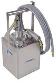
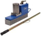
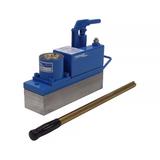
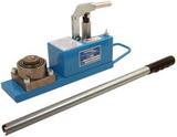
The Tronair 02-7813C0100-A5 is a 12-ton (10.8 metric tons), two-stage hydraulic axle jack designed to lift and support aircraft during routine maintenance, repairs, and other ground operations. Built on a sturdy steel construction with a Tronair Blue painted finish, it features a two-stage hydraulic extension, a two-stage mechanical extension, and a single-speed manually operated pump with a preset relief and release valve. At 17” long and 4” wide, this hydraulic axle jack is a compact, field-ready solution for aircraft maintenance operations across a range of aircraft types.
The Tronair 02-7813C0100-A5 hydraulic axle jack has a vertical lifting capacity of 24,000 lbs (106.75 kN), equivalent to 12 tons or approximately 10.8 metric tons. This rating reflects the maximum safe working load under normal operating conditions, and operators should never exceed this capacity during any lifting operation. For annual load testing, the test load must not exceed the jack's rated capacity plus 10%, and the jack must always be tested under load rather than against the jack itself.
The Tronair 02-7813C0100-A5 has a minimum closed height of 4.63” (11.76 cm) and achieves a maximum height of 15.13” (38.43 cm) when fully extended. The two-stage mechanical extension provides 4.5” (11.43 cm) of additional height adjustment, while the two-stage hydraulic extension delivers 6” (15.24 cm) of lift. This combination of mechanical and hydraulic reach gives technicians precise control over lift height, allowing the jack to be positioned close to the aircraft jack pad before final height adjustment using the mechanical extension.
The Tronair 02-7813C0100-A5 is specifically designed to operate with MIL-PRF-5606 or MIL-PRF-83282 hydraulic fluid only – operators should not use any other fluid type in this unit. Before each use, technicians should verify that the fluid level is between 1/2" and 3/4" from the top of the reservoir fitting and that the rams are completely collapsed. During routine maintenance, all old hydraulic fluid and dirt should be completely flushed from the system and replaced with fresh, clean fluid to maintain proper system performance and prevent internal component damage.
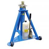
To raise an aircraft with the 02-7813C0100-A5, place the jack on a hard, level surface and raise it as close to the aircraft jack pad as possible, then screw out the center mechanical extension for final height adjustment. Open the reservoir vent screw before operating – this step is mandatory and must never be skipped. Once properly positioned with the mechanical extension in place, close the pump release valve and operate the hand pump to hydraulically raise the aircraft to the desired height. Hands must never be placed between the aircraft and the jack pad during any phase of the lifting operation.
Lowering an aircraft with the 02-7813C0100-A5 is controlled by the pump release valve; loosen it slightly to allow the aircraft to descend slowly and under control. Operators should avoid opening the release valve too quickly, as an uncontrolled descent can cause damage to the aircraft, the jack, or nearby personnel. Always ensure all personnel and equipment are clear of the aircraft's path before beginning the lowering procedure, and monitor the descent continuously until the aircraft is fully supported by its own landing gear.
Two critical cautions apply to every operation of the 02-7813C0100-A5: never place hands between the aircraft and the jack pad, and always open the reservoir vent screw before operating the jack. Beyond these mandatory precautions, the jack must be placed on a hard, level surface to prevent instability under load, and jacking adapters must be appropriate for the specific aircraft being serviced. Employers are responsible for providing a training program that covers safety procedures for the use of the unit in and around the intended aircraft at the servicing location, and for ensuring that all maintenance and troubleshooting are performed exclusively by skilled and trained technicians.
The two primary troubleshooting categories for the 02-7813C0100-A5 are failure to rise (or erratic rising) and failure to lower. If the ram will not rise or rises erratically, probable causes include high-pressure leaks at joints or plugs, a leaky discharge check valve, a leaky ram O-ring seal, a closed air vent, air trapped under the rams, or a plugged inlet diffuser – each with specific corrective actions including retightening, repairing the pump, replacing seals (K-1934 kit), or replacing the inlet diffuser (H-2679). If the jack will not lower or lowers slowly, technicians should check for a closed air vent or release valve, a broken pump release valve, a bent ram, or a plugged inlet diffuser as the most likely causes.
Routine maintenance of the 02-7813C0100-A5 includes regularly verifying hydraulic fluid levels, inspecting all nuts, bolts, and screws for tightness, and periodically flushing and replacing hydraulic fluid. When O-rings and backup rings are removed during servicing, they must always be replaced – cut and damaged rings result in fluid leakage, and every effort must be made to avoid tool contact with the critical sealing surfaces of internal components. Cap screws must be torqued to 50 to 55 ft-lbs during jack reassembly, and all modifications that would adversely affect compliance with applicable standards are prohibited without Tronair's written approval.


