


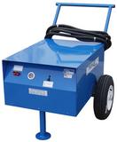
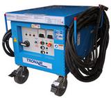
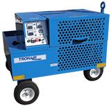
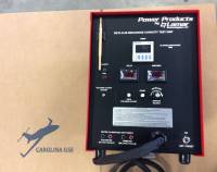
Tronair 11-6610-6000 Superseder III Battery Charger/Analyzer (CE)


Create yours now for free.

Need a Quote?
The Tronair 11-6610-6000 Superseder III Battery Charger/Analyzer is a precision instrument designed to charge and analyze nickel-cadmium, lead-acid, and other rechargeable aircraft batteries, as recommended by the battery manufacturers.
The simple-to-set controls plus the condensed operating procedure found on the front panel make the Superseder III a very easy-to-operate test instrument which – combined with easy-to-read Current, Voltage, Time, and Status indicators – also makes it a very simple one to monitor.
Also designed for speed, the Superseder III can simultaneously charge two batteries (or any number of batteries where the total number of cells is 50 or less), discharge two batteries at reduced currents, or charge one battery (25 cells or less) at maximum current (limited by power dissipation).
The Superseder III provides a Voltage Control enhancement that allows the charger/analyzer – originally designed for Constant Current operation on nickel-cadmium batteries to also be able to handle lead-acid and other types of rechargeable batteries – where the end voltage is a more reliable indicator of the state of charge.
Dependability is another great plus. The Superseder III's 100% solid-state circuitry requires no scheduled maintenance. No relay contacts to inspect and clean. No high-current-carrying contacts to arc and burn. A simple performance verification procedure is all it takes to determine if the instrument requires recalibration or repair.
The unit is also protected against certain internal performance deviations and programming errors; plus, it's also designed to sense certain battery abnormalities to protect the instrument and battery from possible damage. If any malfunction takes place, VISUAL and AUDIBLE indicators will turn on, alerting the operator and preventing any further operation of the unit.
The Superseder III charger/analyzer system comprises the Charger/Analyzer, the Temp-Plate, the Battery Cable, and the Single-Cell Adapter.
The system is essentially a precision-programmable constant current source (for charge) and a programmable constant current sink (for discharge) combined with voltage and temperature-sensing circuits for total battery monitoring.
The specially designed circuitry provides a performance not achieved by any of the older conventional battery-charging methods It will deliver current into a short circuit or a battery or combination of batteries totaling 50 cells, within ±1% of the programmed value, independent of line voltage variations (within ±10% of the nominal line voltage).
The control circuitry of the Charger/Analyzer consists of a Control Processor, a Clock Timer, a Voltage/Current Control, a Voltmeter/Ammeter, a Power Control Board, and a Transformer Control.
The Control Processor receives the function commands from the various function selectors on the Front panel and outputs control signals to the rest of the circuit boards and ultimately to the Charge/Discharge Banks.
The Timer displays the elapsed time for all of the tests performed. Digital time and speed selectors provide the external inputs, while the four-digit readout of the Clock provides the elapsed time display.
The Voltage/Current Control circuit board interprets the programmed current values and controls the conduction of the SCRs and transistors to maintain a constant current in accordance with the feedback received from a precision shunt. It also provides the functions that regulate the charging current in the Constant Voltage (float) mode and in the Peak Voltage mode, transfers from Main to Topping charge on a voltage peak or ends charging on a voltage peak.
Display of current is provided by an independent Digital Ammeter that uses the same shunt used by the Voltage/Current control circuit.
Inputs from the Timer and the Control Processor determine the operating mode of the Current Control circuit.
The System Monitor within the Control Processor provides several safeguarding functions. It compares the measured current against the programmed value and if they differ beyond what the software allows, the operation is halted and a current malfunction is indicated.
The system measures the battery voltage and compares it with the programmed number of cells. From there, it determines during charge if the total voltage exceeds the equivalent of 1.75 volts per cell, indicating an overvoltage condition, or during discharge if the total voltage is below the equivalent of 1 volt per cell, indicating the end of the discharge cycle.
It checks for polarity reversal at voltages as low as 0.25V, as well as an absolute overvoltage at about 42V/85V, both generating a voltage malfunction indication that prevents any further operation of the unit.
It measures the temperature of the discharge heat dissipators and signals an overheat malfunction if the internal temperature exceeds 90°C, as it could be caused by a fan failure or an installation with restricted airflow. It also monitors the temperature of the batteries being charged (via the Temp-Plate) and terminates the charge, indicating battery Overtemp, in the event of battery overheating that may lead to thermal runaway.
The Digital Voltmeter provides internal battery voltage readings with resolutions of 0.1V and 0.01V, while a selectable external position allows single-cell measurements to a resolution of 0.001V.
Additional protection is provided by a high-speed current limiter for the discharge transistor bank, a slow-speed current limiter for the charge circuit, and a magnetic circuit breaker capable of tripping under fast high current overload conditions.
The Charger/Analyzer is also equipped to communicate and be controlled by the BTAS16, Computerized Battery Test System.
Specifications
- Adjustable Current Flow: 0 to 50 Amps
- Input Voltages: 208V / 230V AC – 50/60 Hz
- Dimensions: 19" L x 20" W x 15" H (48 x 51 x 38 cm)
- Weight: 120 lbs (54 kg)
| General Information | |
|---|---|
| Part # | 11-6610-6000 |
| Manufacturer | Tronair |
| Shipping Information | |
|---|---|
| Shipping Weight | 200 lbs. |
| Shipping Dimensions | 37 x 37 x 27 in. |
| Freight NMFC | 61700 |
| Schedule B | 8504409580 |
| ECCN | EAR99 |
Customers also viewed

Customers who bought this item also purchased


AIRCRAFT COMPATIBILITY
PRODUCT REVIEWS
This item does not have any reviews yet.
QUESTIONS & ANSWERS
The Superseder III is designed for servicing, conditioning, and analyzing nickel-cadmium (Ni-Cd) aircraft batteries in maintenance environments. It automatically monitors voltage, current, and temperature throughout charging and discharging cycles. By combining precise control with automatic protection circuits, the unit ensures safe, efficient restoration and evaluation of battery performance.
This model is primarily engineered for nickel-cadmium aircraft batteries, ranging from single cells to 50 cells connected in series. It can also discharge and test two separate batteries simultaneously, provided total current draw remains below 20 amps. The system’s flexible current control accommodates a wide range of aviation battery capacities.
A built-in thermistor-based circuit continuously monitors cell temperature during charge and discharge. If a battery overheats, the charger automatically reduces or stops current flow to prevent thermal runaway and plate damage. This closed-loop temperature protection ensures reliable performance and extends battery life.
The Superseder III accepts 208V or 230V AC input at 50 or 60 Hz, allowing use in both U.S. and international maintenance facilities. A dedicated circuit with proper grounding and surge protection is recommended. Due to its 120-lb weight and bench-mounted form factor, the unit should be installed in a stable, well-ventilated work area.
Before connecting, verify that each cell’s electrolyte level is correct, terminals are clean, and inter-cell connectors are tight. Inspect the battery for leakage or swelling. Once connected, follow the prescribed polarity and cell-count settings to prevent reverse charging or imbalance during analysis.
Yes. The system is capable of servicing up to 50 cells in one battery or two batteries in parallel, with total current limited to 20 amps during simultaneous discharge. This multi-battery capability enables efficient maintenance workflows for busy MRO facilities while maintaining precise current regulation across each circuit.
The analyzer utilizes a controlled-load circuit to discharge batteries at a set current until the voltage reaches a user-defined cutoff. During this phase, it logs voltage response and temperature, providing valuable data on battery capacity and health. Automatic shutdown prevents overdischarge, which could harm the cells.
Routine checks include verifying fan operation, cleaning exterior vents, inspecting power cords, and confirming calibration accuracy of the ammeter and voltmeter. All maintenance should be performed with the unit powered off and unplugged from the power source. Tronair recommends periodic functional testing to ensure that the safety interlocks and sensors respond properly.
Operators should wear protective gloves and eye shields when handling Ni-Cd cells, as the electrolyte is caustic. Always maintain adequate ventilation to dissipate gases generated during charge cycles. Never bypass the automatic temperature or over-voltage protection – these systems prevent serious hazards, such as venting or thermal damage.
Calibration of current and voltage measurement circuits should be verified annually using traceable laboratory standards. Adjustments can be made through internal trim controls following Tronair’s service instructions. Maintaining calibration ensures accurate capacity readings and compliance with aviation maintenance documentation requirements.
Store the unit in a dry, dust-free area at moderate room temperature. Disconnect all cables and keep the front panel covered to protect switches and meters. Avoid prolonged exposure to vibration or corrosive environments, as these can affect circuit reliability and the chassis finish.


