


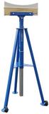
1730012732435 - Tronair 06-4035-3600 – 8-Gallon Hydraulic Component Test Cart – Skydrol/PE Fluids


Create yours now for free.
The 1730012732435 is a specific part number of the series Tronair 06-4035-3600. For more generalized information on this item series or for more options, click here.

Need a Quote?
| Alternate Models | |
|---|---|
| 06-4035C3600 | CE Rated |
| 06-8012-3600 | Previous Part Number |
| 1730012732435 | National Stocking Number (NSN) |
| GSB1210004 | Bombardier GSE Part Number |
| General Information | |
|---|---|
| Part # | 1730012732435 |
| Manufacturer | Tronair |
| NSN | 1730012732435 |
| Manual 1 | View Tronair 06-4035-3600 Parts, Service, and Operating Manual |
| Shipping Information | |
|---|---|
| Shipping Weight | 83 lbs. |
| Shipping Dimensions | 37 x 24.5 x 28.5 in. |
| Freight NMFC | 128000 |
| Schedule B | 8413600040 |
| ECCN | EAR99 |
Customers also viewed


Customers who bought this item also purchased

AIRCRAFT COMPATIBILITY
PRODUCT REVIEWS
QUESTIONS & ANSWERS
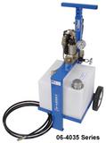
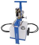
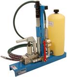
With its high/low manual pump, the 06-4035-3600 delivers a maximum output pressure of 4,000 PSI. This makes it versatile enough to support tasks such as brake bleeding, component testing, and system pressurization. A shut-off valve ensures operators can hold pressure safely during tests.
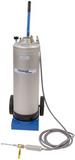
The unit is equipped with wheels and an adjustable handle for easy maneuverability. Its compact frame allows technicians to move it around hangars and ramps without difficulty. Despite its mobility, the unit remains stable during use, preventing spills or unintentional movement.
The cart is shipped fully assembled, but operators must fill the reservoir with clean, approved fluid before use. It’s also necessary to remove any air from the system by following the manufacturer’s priming procedure, which includes bleeding the pump and checking the shut-off valve. Proper preparation ensures consistent hydraulic pressure and prevents system failures during servicing.
Yes, the 06-4035-3600 includes a shut-off valve that prevents backflow and allows technicians to hold pressure for testing hydraulic components. This feature makes it ideal for maintenance tasks that require steady, repeatable pressure. Pressure can then be safely relieved by opening both the valve and the release screw.
The unit has a pressure gauge for monitoring system pressure and a shut-off valve that prevents uncontrolled backflow. Dust plugs are also included to keep hoses clean and free of contaminants when not in use. These features help maintain safe and reliable operation in busy maintenance environments.
According to Tronair, the included pressure gauge should be recalibrated on a periodic basis determined by the operator’s quality system or regulatory requirements. Calibration ensures accuracy in testing and servicing aircraft components. Certificates of calibration are supplied with the unit for reference.
Yes, the manual pump handle can be adjusted to suit the operator’s height, making it easier to use over long service intervals. This ergonomic design reduces fatigue and improves efficiency during repeated hydraulic pumping. Proper handle adjustment also allows for smoother, more controlled pressure application.
Once maintenance is finished, operators should open the pump release screw to relieve system pressure. The hose should then be disconnected and capped with its dust plug to prevent contamination. Following these steps helps extend the service life of both the hydraulic cart and the aircraft system being serviced.
Unlike generic hydraulic service units, the 06-4035-3600 is purpose-built for aircraft maintenance tasks such as brake bleeding, reservoir filling, and component testing. Its compact size, high-pressure capability, and specialized compatibility with phosphate ester fluids make it well-suited for aviation environments. Tronair’s reputation for durable, field-proven ground support equipment further enhances its reliability.
Draining the hydraulic fluid from the Tronair 06-4035-3600 Hydraulic Service Unit can be done safely using one of several approved methods, depending on whether the unit is operational and the rate at which you need to remove the fluid.
- If the pump is functioning, use the unit’s manual pump to push the old fluid out through the service hose and into a suitable container. (This is the simplest method.)
- Remove the reservoir fill cap and carefully tip the unit or the reservoir upside down to let the fluid drain out by gravity.
- Disconnect the hydraulic hoses and lift the reservoir out of the frame, as it rests in place and is not bolted down. Once removed, you can fully empty the tank by inverting it.
Each approach ensures proper fluid removal before filter replacement, system flushing, or scheduled maintenance.


